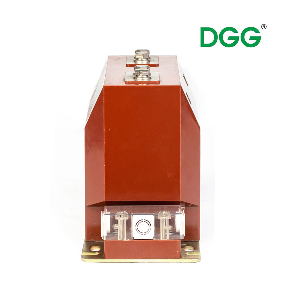
High-voltage circuits carry immense amounts of energy. You cannot connect sensitive metering devices or protection relays directly to these primary lines. A properly specified current transformer bridges this dangerous gap safely. It steps down massive primary currents into standardized, manageable secondary values.
Making the wrong selection introduces severe operational risks. An incorrect unit may saturate under severe fault conditions. This failure blinds your protection systems exactly when you need them most. Poor choices also cause severe measurement inaccuracies and trigger heavy installation delays. Engineers must clearly understand how different electrical environments demand specific core types and exact accuracy profiles.
This article provides a rigorous breakdown of available transformer types. We will explore core evaluation criteria and highlight hidden implementation risks. You will learn how to calculate secondary burden, prevent secondary circuit hazards, and recognize when standard options fall short. This technical guide equips you to make robust engineering and procurement decisions.
Key Takeaways
Application Dictates Type: Wound, toroidal, bar, and split-core current transformers each serve distinct load requirements and installation environments.
Accuracy vs. Feasibility: Retrofitting often requires split-core models, but engineers must account for the inherent accuracy trade-offs compared to solid-core toroidal models.
Specification goes beyond ratio: Evaluating burden, accuracy class (metering vs. protection), and saturation limits is non-negotiable for system compliance.
Customization solves integration gaps: A custom current transformer is often required for non-standard busbar configurations or extreme environmental tolerances.
Evaluating the Primary Types of Current Transformers
Engineers categorize current transformers based on their physical construction and primary winding mechanisms. Each design category solves specific application challenges. You must weigh technical performance against installation feasibility.
Wound Current Transformers
In a wound unit, the primary winding consists of multiple turns physically connected in series inside the main circuit. The conductor carrying the measured load current flows directly through this primary coil.
Best For: We typically specify wound models for low-current applications requiring exceptionally high measurement precision. They excel in scenarios demanding exact ratio step-downs for sensitive meters.
Trade-offs: The internal primary winding creates a localized bottleneck. These units remain highly susceptible to thermal stress during high fault currents. They also occupy a significantly larger physical footprint inside electrical panels.
Toroidal (Window) Current Transformers
Toroidal models contain no internal primary winding. The core takes a ring or window shape. The live main conductor routes directly through the center hole. This passed-through cable acts as a single-turn primary winding.
Best For: These units dominate standard new-build installations and OEM equipment designs. They offer highly accurate metering profiles due to their continuous, unbroken magnetic core.
Trade-offs: Installation requires disconnecting the primary circuit to feed the cable through the window. This highly disruptive process makes toroidal models difficult to implement during live facility retrofits.
Bar-Type Current Transformers
Bar-type units use the actual main cable or rigid busbar as the primary winding. The transformer core wraps around this heavy-duty primary bar. They handle massive loads without burning out.
Best For: We utilize bar-type models in heavy-duty, high-current environments. You will find them primarily in utility substations, generator outputs, and large industrial switchgear assemblies.
Trade-offs: These designs are exceptionally bulky and heavy. They require robust mechanical mounting structures to withstand violent electromagnetic forces generated during short-circuit events.
Split-Core Current Transformers
Manufacturers design the magnetic core in two distinct halves. You can physically separate the core, place it around an existing live conductor, and snap it securely back together.
Best For: Split-core models shine during facility upgrades and energy auditing projects. They provide an excellent solution for retrofits where powering down the entire system remains financially or logistically impossible.
Trade-offs: The mechanical split introduces a microscopic air gap into the magnetic path. This gap causes inherent magnetic losses. Split-core units generally deliver a lower accuracy class compared to solid-core toroidal counterparts.
Quick Selection Chart
Transformer Type
Primary Mechanism
Ideal Application Environment
Primary Limitation
Wound
Coil connected in series
Low-current, high-precision metering
Thermal stress under faults; bulky
Toroidal
Cable passes through window
New builds, OEM switchgear
Circuit disconnection required
Bar-Type
Busbar acts as primary winding
Utility substations, heavy industry
Heavy weight; needs rigid mounting
Split-Core
Core opens to clamp around cable
Live retrofits, energy audits
Lower accuracy due to air gap
Performance Dimensions: How to Specify the Right Unit
Specifying a transformer goes far beyond choosing a simple current ratio. You must evaluate the magnetic performance limits and thermal boundaries of the unit. Relying solely on ratio assumptions leads to catastrophic relay failures.
Accuracy Class (Metering vs. Protection)
Engineers must sharply distinguish between metering profiles and protection profiles. They operate under fundamentally different magnetic conditions.
Metering classes demand extreme accuracy under normal, nominal load conditions. You use these for revenue billing and daily energy monitoring. However, a metering core deliberately saturates quickly during a fault. This intentional saturation protects sensitive digital meters from receiving massive current spikes.
Protection classes must maintain a linear output during massive fault currents. Relays rely on this linear signal to detect the true magnitude of a short circuit. If a protection core saturates too early, the relay sees a clipped waveform. It might fail to trip the circuit breaker. You must always match the accuracy class to the intended end-use device.
Burden (VA Rating)
Every device connected to the secondary winding draws power. This connected load is called the burden. You measure burden in Volt-Amperes (VA) or total Ohms of impedance. The transformer must push the secondary current through this impedance without losing magnetic accuracy.
To calculate and verify the total secondary burden, follow these procedural steps:
Measure wiring resistance: Calculate the total resistance of the copper wire running from the transformer terminals to the control panel. Long wire runs add significant impedance.
Check device specifications: Identify the internal impedance ratings of every connected meter, relay, and transducer on the loop.
Sum the total load: Add the wire resistance to the equipment impedance to find the total operating burden.
Compare against standard limits: Ensure your calculated total remains strictly below the transformer’s nameplate VA rating.
Continuous Thermal Current Rating Factor (RF)
The rating factor (RF) defines how much continuous overload the unit can handle safely. An RF of 1.5 means the transformer can operate continuously at 150% of its nominal rating. It does this without exceeding its safe temperature rise limits.
You must evaluate this factor carefully. Industrial facilities frequently upgrade operations. Base load currents often creep upward over time. A higher rating factor accommodates future capacity expansions safely. It prevents premature insulation breakdown caused by chronic overheating.
Implementation Realities and Installation Risks
Theoretical specifications mean little if installation practices compromise safety. Electrical teams face severe hazards during commissioning. You must understand common failure modes and environmental bottlenecks to ensure system integrity.
The Open-Secondary Hazard
You face a lethal safety hazard if you leave a secondary winding open-circuited while the primary remains energized. This strict rule governs all current transformer operations.
Under normal conditions, the secondary current creates a magnetic flux. This secondary flux opposes the primary flux. It keeps the core balanced. If you open the secondary circuit, the opposing flux drops to zero. The core immediately magnetizes to saturation. This massive flux shift induces thousands of volts across the open secondary terminals.
These lethal voltage spikes destroy wire insulation instantly. They cause arcing across terminal blocks. They present a massive electrocution hazard to anyone nearby. You must always short-circuit the secondary terminals before performing maintenance on connected relays or meters.
Core Saturation Risks
Saturation blinding represents a critical failure mode in protection schemes. An asymmetrical fault current often contains a transient DC offset. This DC component pushes the magnetic core toward its physical flux limit much faster than a standard AC wave.
Once saturated, the transformer stops reproducing the primary waveform accurately. The secondary output drops. The protection relay reads a falsely low current value. It assumes the fault has cleared or never occurred. The breaker fails to trip, allowing the fault to destroy downstream equipment. You must size protection cores to handle these asymmetrical transients.
Environmental Constraints
Field installations rarely match ideal engineering blueprints. Physical and environmental constraints dictate your final hardware selection. Consider these practical best practices:
Verify panel footprint: Legacy switchgear often lacks space for standard bulky units. Measure physical clearances carefully before ordering.
Respect bending radii: Heavy primary cables possess a minimum bending radius. Do not force thick cables into awkward angles just to pass them through a toroidal window.
Check ambient temperatures: Enclosed panel temperatures run high. High ambient heat severely degrades transformer insulation ratings over time.
Assess vibration levels: Units installed near heavy rotating machinery require specialized vibration-resistant mountings to prevent terminal fatigue.
When to Specify a Custom Current Transformer
Standard catalogs cover most general applications. However, complex engineering challenges frequently demand bespoke solutions. You must recognize when an off-the-shelf unit introduces unacceptable compromises.
Identifying the Tipping Point
Several scenarios push engineers toward custom solutions. Legacy switchgear retrofits often feature non-standard busbar dimensions. Standard toroidal cores simply will not slide over these strange shapes. You might also encounter highly specific primary-to-secondary ratio requirements. Strict space constraints inside dense electrical panels frequently rule out mass-produced, bulky options.
Evaluating Custom Manufacturers
Procuring a custom current transformer requires careful vendor vetting. Do not select a manufacturer based purely on quoted lead times. You must evaluate their core engineering capabilities.
Look for vendors possessing robust in-house testing laboratories. They must guarantee adherence to strict IEEE C57.13 or IEC 61869 standards. Ask about their rapid prototyping timelines. A competent manufacturer will supply physical dimensional models quickly. This lets you verify physical fitment before committing to full production runs.
Information Required for a Custom Build
Clear communication prevents costly manufacturing errors. When engaging a custom vendor, you must provide a comprehensive technical specification package. Use the following checklist to ensure accurate procurement:
Exact window dimensions: Provide the physical size and shape needed to clear your specific busbars or cables.
Required ratio: Detail the primary load current and the exact secondary output needed (e.g., 5A or 1A).
Operating voltage and frequency: Specify the system voltage level and whether the network operates at 50Hz or 60Hz.
Accuracy class: State clearly whether the unit serves a metering or protection function, including the required precision standard.
Burden requirements: Provide the total expected secondary VA load.
Environmental IP ratings: Detail any requirements for moisture resistance, dust ingress protection, or extreme temperature tolerance.
Conclusion
Selecting the right transformer requires a calculated balance. You must weigh operational measurement accuracy against actual installation feasibility. You must never compromise system safety to save panel space.
Engineers must look past the initial hardware specifications. Evaluating installation downtime and long-term protection reliability proves crucial for ultimate system success. A poorly sized unit guarantees future relay failures and dangerous operational blind spots.
We strongly encourage engineering teams to consult proactively with specialized manufacturers. Share your complete single-line diagrams with technical sales teams early in the design phase. Reviewing these schematics together ensures you finalize the safest, most accurate specifications for your specific network architecture.
FAQ
Q: What happens if a current transformer is undersized for the burden?
A: The transformer cannot generate enough voltage to push the secondary current through the excessive impedance. The core saturates prematurely. This severely degrades measurement accuracy. In protection circuits, this failure prevents relays from detecting massive faults, stopping the breaker from tripping and exposing the network to catastrophic damage.
Q: Can I use a metering current transformer for relay protection?
A: No. Doing so introduces a major safety risk. Metering cores saturate intentionally at lower fault levels to protect sensitive instruments. If used for protection, the core will saturate during a short circuit. The protection relay will read a falsely low current and fail to isolate the fault.
Q: How much accuracy is lost when using a split-core current transformer?
A: The physical air gap introduces magnetic reluctance, causing phase angle errors. You can typically expect an accuracy class drop to between 1% and 3%, depending on the manufacturer's machining tolerances. High-end models minimize this gap, but they rarely match the 0.2% precision of solid toroidal cores.