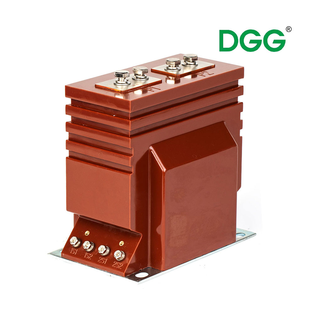
Procuring high voltage equipment carries enormous stakes for any power infrastructure. A single specification error can easily lead to catastrophic grid failures. Facilities might also face massive revenue metering losses or severe safety hazards. Many teams mistakenly treat this procurement process as a basic technical checklist. In reality, it represents a critical long-term asset investment. You need perfect alignment between engineering specifications, physical site realities, and vendor reliability.
This article provides a structured evaluation framework for the decision stage. You will discover exactly how to select the right equipment for your substation. We will also highlight common specification pitfalls you must avoid. You will explore core technical parameters, strict insulation requirements, and important customization options. Ultimately, we aim to ensure your grid remains secure, compliant, and highly efficient for decades.
Key Takeaways
Matching the accuracy class and burden to the specific application (metering vs. protection) is the foundation of preventing core saturation.
High voltage environments dictate strict insulation requirements; dielectric strength and partial discharge testing are non-negotiable.
Off-the-shelf units often fall short in retrofit scenarios, making a custom current transformer the more cost-effective long-term solution despite higher initial CapEx.
1. Defining Core Technical Parameters for Your Application
Every successful procurement project begins here. You must define the precise electrical parameters governing your grid. Failing to establish accurate baselines leads to dangerous equipment misapplication. Selecting a reliable current transformer requires a deep understanding of your primary load and secondary relay requirements.
Primary and Secondary Current Ratio
Sizing the current ratio correctly requires strategic foresight. Many engineers overestimate future load growth. This overestimation degrades low-end accuracy significantly. If you specify a 2000:5 ratio for a circuit only drawing 200 amps, the unit operates at the extreme low end of its curve. Metering accuracy plummets at this level. You should size the primary current close to the maximum expected continuous load. This approach guarantees optimal precision during normal daily operation.
Accuracy Class Designation
You must separate metering requirements from protection requirements. They serve entirely different functions. Metering cores demand high accuracy under normal load conditions. You will typically specify IEEE 0.15s or 0.2s classes for revenue billing. These ensure utilities capture every drop of energy used. Protection cores focus strictly on reliability during massive fault conditions. They use relay classes like IEEE C-class or IEC P-class. Protection cores must not saturate when massive short-circuit currents flow through the system. They must accurately drive protective relays to trip breakers instantly.
Burden (VA Rating)
The burden represents the total load connected to the secondary terminals. You must calculate this precisely to prevent secondary voltage collapse. If the burden exceeds the rated capacity, the core saturates prematurely. This saturation blinds your protective relays.
To calculate the total burden accurately, follow these critical steps:
Calculate the resistance of the secondary cabling over its entire run length.
Determine the load of all connected protective relays.
Add the input impedance of any revenue meters on the circuit.
Sum these values and include a 20% safety margin for future additions.
Thermal and Dynamic Short-Time Current
High voltage networks experience violent short circuits. Your equipment must survive these events physically and thermally. We evaluate this through thermal and dynamic short-time current ratings. The thermal rating dictates how much fault current the unit can handle for a specific duration. You typically see 1-second or 3-second ratings. The dynamic rating measures mechanical resilience. Huge electromagnetic forces try to tear the internal windings apart during a fault. Verifying these ratings ensures your equipment stays intact during severe system disruptions.
2. Insulation, Cooling, and Environmental Resilience
High voltage environments relentlessly stress physical materials. Insulation integrity directly determines equipment lifespan. You must match the insulation medium to your specific environmental realities.
Dielectric Strength and Insulation Mediums
Dielectric strength prevents high voltage from bridging the gap to the grounded chassis. You have three primary insulation options available. Each offers distinct advantages based on voltage levels and facility maintenance capabilities.
Insulation Medium Comparison Chart
Insulation Medium
Typical Voltage Range
Key Advantages
Maintenance Requirements
Oil-Immersed
69kV to 765kV+
Excellent cooling, proven long-term reliability.
Requires periodic Dissolved Gas Analysis (DGA) and oil sampling.
SF6 Gas
115kV to 500kV
Non-flammable, compact footprint, superior dielectric strength.
Strict gas pressure monitoring; environmental handling compliance.
Cast Resin (Dry Type)
Up to 69kV
Zero leak risk, fire-resistant, very low maintenance.
Visual inspections for surface tracking or micro-cracks.
Creepage Distance and Pollution Class
Site-specific environmental conditions dictate external design. You must evaluate the pollution class of your installation site. Coastal facilities face heavy salt fog. Industrial sites deal heavily in conductive dust. High altitude installations suffer from reduced air density. These factors require extended creepage distances. Creepage is the shortest path along the insulator surface between the high voltage terminal and the ground. Specifying highly rated polymer or porcelain sheds prevents external flashovers. You must adapt the creepage distance to match your exact regional pollution severity.
Standard Compliance
Interoperability and safety rely entirely on strict standard adherence. You cannot compromise here. North American projects generally demand IEEE C57.13 compliance. International projects require adherence to IEC 61869-2. These frameworks dictate rigorous testing protocols, thermal limits, and accuracy definitions. Specifying these standards in your procurement documents legally binds the manufacturer to a recognized baseline of quality. It ensures your newly purchased assets integrate flawlessly into existing grid infrastructure.
3. Standard vs. Custom Current Transformer: Making the Right Call
Engineers often debate between catalog models and bespoke engineering. Standard units offer quick delivery times. However, complex substations frequently demand highly tailored solutions.
When to Specify Custom
Off-the-shelf equipment rarely fits smoothly into older infrastructure. You often encounter non-standard dimensional constraints during retrofit projects. Gas Insulated Substations (GIS) are notoriously tight spaces. Compact urban substations lack the physical footprint for standard porcelain towers. In these scenarios, specifying a custom current transformer becomes essential. Custom designs also solve complex electrical demands. You might need multi-ratio tap configurations to accommodate phased load growth. You might also require extreme ambient temperature tolerances for desert or arctic deployments.
Cost-Benefit Analysis
Custom engineering naturally involves higher upfront costs. You face extended lead times while manufacturers draft 3D models. However, you must weigh these initial hurdles against long-term operational savings. A perfectly engineered custom unit drops directly into existing mounting pads. It eliminates expensive civil engineering rework at your site. It prevents costly busbar modifications. Over a 30-year operational lifespan, the exact-fit reliability of a tailored solution vastly outweighs the initial engineering premium.
Vendor Engineering Capabilities
You must rigorously assess the manufacturer before requesting bespoke designs. Not all vendors possess true custom capabilities. Reliable partners provide detailed 3D CAD modeling upfront. They offer transparent design iteration processes. They construct prototypes and validate them before beginning full production runs. You should request case studies of their previous custom retrofit projects. This vetting process ensures they can actually deliver on their engineering promises.
4. Common Selection Errors and Implementation Risks
Even seasoned engineers occasionally stumble during the specification phase. Avoidable errors cause catastrophic relay failures or costly billing disputes. Recognizing these pitfalls keeps your project secure.
Under-sizing the Burden
Failing to account for the total secondary circuit length is incredibly common. Engineers often calculate relay impedance but forget the long cable runs reaching the control room. This oversight under-sizes the burden capacity. When a fault occurs, the secondary voltage spikes. The core saturates instantly. The protective relay never receives the trip signal. The breaker stays closed. This exact scenario destroys massive power transformers every year.
Mixing Protection and Metering Specs
Accuracy classes are not interchangeable. Using a protection-class core for revenue metering causes massive financial loss. Protection cores lack precision at very low currents. The utility essentially gives away unmetered power during light load periods. Conversely, using a metering-class core for protective relaying is incredibly dangerous. Metering cores intentionally saturate early to protect delicate digital meters from high fault currents. If you wire a relay to a metering core, it goes blind right when you need it most.
Overlooking Factory Acceptance Testing (FAT)
Never accept delivery of high voltage equipment without verified testing data. Routine factory tests separate reliable assets from imminent failures. You must demand comprehensive FAT reports.
Partial Discharge Testing: Identifies microscopic internal voids. These voids cause insulation breakdown over time.
Lightning Impulse Testing: Verifies the unit can survive severe atmospheric overvoltages and switching surges.
Accuracy and Phase Angle Testing: Confirms the unit performs exactly as specified across its entire load range.
Temperature Rise Testing: Ensures the internal windings do not exceed safe thermal limits under continuous maximum load.
5. Vendor Shortlisting Logic
Evaluating the unit purchase price is only the beginning. You must assess how the vendor supports the equipment throughout its entire operational lifecycle. Strong vendor partnerships prevent extended operational downtime.
Lifecycle Maintenance
High voltage equipment requires dedicated maintenance programs. Oil-filled units demand regular Dissolved Gas Analysis (DGA) testing. This tracks internal degradation before failures occur. SF6 units require precise gas pressure checks and leak detection protocols. You must evaluate how easily your maintenance teams can perform these tasks. The vendor should provide clear maintenance manuals, accessible testing ports, and straightforward sampling valves. Complex, proprietary maintenance procedures drain your operational budget rapidly.
Warranty and Post-Sales Support
Always evaluate the warranty length and terms. A standard one-year warranty offers little comfort for an asset expected to last three decades. You should look for vendors offering extended guarantees. Furthermore, assess their post-sales support infrastructure. Do they maintain domestic inventory for critical replacement parts? What is their guaranteed field service response time? A massive grid outage requires immediate technical intervention. Your vendor must deploy engineering support rapidly when emergencies strike.
Delivery Logistics and Installation
High voltage equipment is massive, heavy, and surprisingly fragile. Internal windings can shift during rough transport. Porcelain insulators crack under stress. Vendor evaluation must include their logistics expertise. You should inquire about their freight securing methods and impact-monitoring sensors used during transit. They must carry comprehensive shipping insurance. Finally, evaluate their installation commissioning support. Reputable vendors dispatch field engineers to oversee the final installation, ensuring your team energizes the equipment safely.
Conclusion
Procuring high voltage current transformers requires balancing strict electrical specifications with rugged environmental foresight. You cannot treat this process lightly. Every parameter, from the protection class designation to the external creepage distance, directly impacts your grid security. Choosing customized solutions often streamlines installation and boosts long-term reliability.
We recommend taking immediate action before requesting any vendor quotes. Compile a comprehensive site-condition report documenting your specific environmental hazards. Update your single-line diagram package to reflect exact secondary burden requirements. Armed with precise data, you can confidently partner with a manufacturer capable of delivering resilient, high-performance equipment.
FAQ
Q: What is the typical lifespan of a high voltage current transformer?
A: A well-maintained unit typically lasts between 25 and 30 years. Lifespan depends heavily on strict adherence to maintenance schedules. Operating the equipment strictly within its rated thermal limits also extends its life. Regular insulation testing helps identify degradation early, allowing for proactive repairs.
Q: How do I know if I need a multi-ratio current transformer?
A: You need a multi-ratio unit if you anticipate significant future load growth in your substation. It features multiple secondary taps. This allows you to adjust the current ratio easily as demand increases. You avoid the massive expense of replacing the entire primary high voltage equipment.
Q: What routine maintenance is required for high voltage CTs?
A: Maintenance involves frequent visual inspections for oil or gas leaks. You should use thermal imaging cameras to detect internal hot spots. Routine diagnostic testing is also essential. You must regularly perform insulation resistance tests, power factor tests, and oil sampling for dissolved gas analysis.
Q: Why is partial discharge testing critical for high voltage CTs?
A: Partial discharge testing detects microscopic voids or impurities hidden deep within the insulation. These tiny defects cause localized electrical stress. Over time, this stress eats away at the insulation. It is the leading early indicator of an eventual catastrophic internal failure.