

Views: 0 Author: Site Editor Publish Time: 2026-06-23 Origin: Site
Power system design hides a critical and often overlooked risk. A highly advanced protective relay is only as reliable as its analog signal. If the incoming data is flawed, the most sophisticated relay fails. During severe high-fault currents, magnetic core saturation drastically distorts secondary waveforms. This distortion blinds protective relays precisely when you need them most. It leads to catastrophic equipment damage and widespread utility outages. Addressing this threat requires evaluating your equipment under extreme conditions.
We present a definitive evaluation framework below. You will learn how to specify and select equipment properly. This approach ensures signal fidelity during extreme transient and steady-state fault conditions. Engineers must understand these dynamics to protect critical infrastructure. We guide you through core evaluations, system variables, and compliance testing. This ensures your electrical networks remain safe, stable, and resilient against unpredictable fault events.
System Integrity: Current transformer saturation causes protection blinding or false tripping, directly compromising safety and operational uptime.
Evaluation Metrics: High anti-saturation performance requires assessing the Accuracy Limit Factor (ALF), knee-point voltage, and transient dimensioning factors.
Compliance & Sizing: Rigorous CT saturation calculations aligned with IEEE/IEC standards are non-negotiable for system validation.
Procurement Strategy: High-fault or space-constrained environments frequently necessitate a custom current transformer over off-the-shelf alternatives.
Understanding the business problem begins with the underlying physics. A magnetic core can only hold a specific amount of magnetic flux. We call the limit the knee point. Below this threshold, the secondary current perfectly mirrors the primary fault current. Once operation pushes beyond the knee point, the core saturates. It stops reproducing the primary signal accurately. The resulting secondary waveform becomes severely clipped and distorted.
This physical limitation creates a massive operational hazard known as protection blinding. When waveform distortion occurs, relays fail to detect genuine faults. The relay measures a smaller current than what actually exists in the primary circuit. Consequently, it delays tripping or fails to trip entirely. You risk the complete destruction of expensive transformers and generators. Fire hazards escalate rapidly under these conditions.
Conversely, saturation also causes transient overreach. This leads to false tripping. Directional and differential relays rely on precise phase angles and current balances. Asymmetrical saturation disrupts this balance. One core saturates faster than another during a through-fault. The relay perceives this mismatch as an internal fault. It issues a trip command unnecessarily. This triggers widespread system shutdowns and isolates healthy network sections.
Inaction carries severe consequences. Under-specifying your Instrument Transformer introduces immense risk. You face massive equipment replacement costs following a failure. Facility downtime halts production. Regulatory bodies issue heavy compliance fines for preventable outages. A resilient power system demands exact engineering at the analog measurement level to prevent these cascading failures.
Evaluating equipment requires an objective framework. You must focus on specific metrics to ensure desired outcomes.
First, we analyze Knee-Point Voltage margins. The knee point dictates the maximum voltage the secondary winding can produce before saturation. Defining the optimal threshold requires precision. You want enough margin to handle the maximum expected fault. However, you must avoid the trap of unnecessary over-sizing. Over-sized equipment wastes money and occupies too much physical space in the switchgear.
Next, you must evaluate core material selection. Standard silicon steel serves general applications well. However, demanding environments require advanced materials. Nanocrystalline or nickel-alloy cores offer vastly superior performance. They provide low remanence and high resistance to magnetic saturation. The table below compares common core materials used in protection applications.
Core Material | Saturation Limit | Remanence Level | Best Use Case |
|---|---|---|---|
Standard Silicon Steel | Moderate (~1.5 to 1.8 Tesla) | High (up to 80%) | General distribution, low transient systems |
Nickel-Alloy | Low (~0.7 to 0.8 Tesla) | Very Low | High-accuracy measurement, specific protection |
Nanocrystalline | High (~1.2 Tesla) | Extremely Low (<10%) | High-fault transient protection, severe X/R conditions |
The Accuracy Limit Factor represents another critical metric. You will see ALF listed on vendor specification sheets. It defines the multiple of rated current up to which the specified accuracy is maintained. You must read these sheets carefully. Ensure the ALF aligns with actual maximum fault currents in your specific network. Relying on nominal loads alone will guarantee failure during a short circuit. Every well-specified current transformer must map its ALF to the worst-case scenario.
Finally, consider the transient response class. IEC standards define specific protection classes to handle DC offsets. Class TPX cores lack an air gap. They hold high remanent flux. Class TPY cores include a small air gap. This gap limits remanence and manages transient DC components effectively. Class TPZ cores feature multiple air gaps. They offer near-zero remanence but introduce significant phase angle errors. You must select the class based on your required DC offset handling and remanent flux decay.
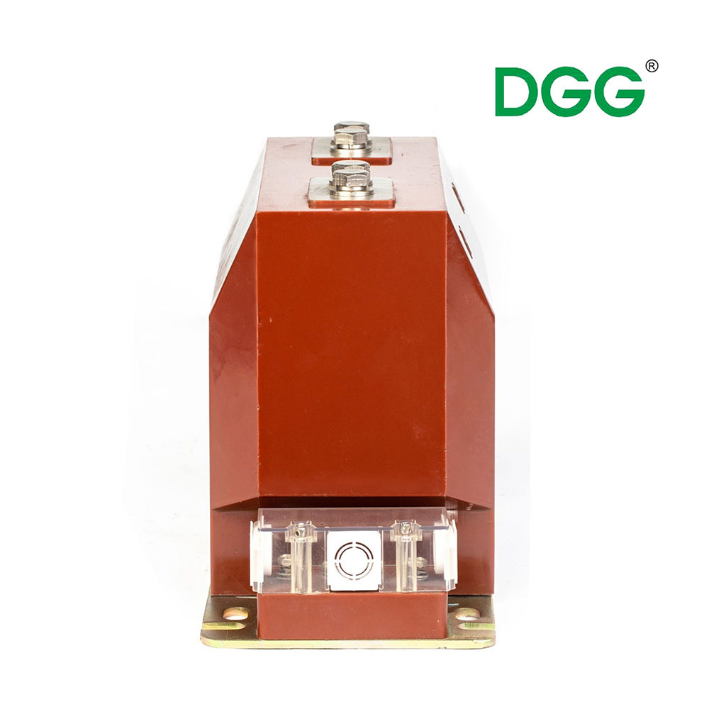
Real-world implementation involves many variable factors. You must account for system conditions to avoid rollout risks. The physical environment heavily influences core behavior.
The X/R Ratio of the Power System: The system reactance to resistance ratio dictates the DC time constant of the fault current. Locations close to large generators exhibit high X/R ratios. High DC time constants demand exponentially higher anti-saturation capabilities. The decaying DC component pushes the magnetic flux in one direction continuously. This forces the core into saturation much faster than AC current alone.
Secondary Burden Variations: The practical saturation point changes dynamically based on connected loads. Relay input impedance plays a role. Lead wire length contributes significantly to the total burden. Terminal connections add resistance. High secondary burden forces the core to generate higher voltage to push the current. This elevated voltage drives the core toward the knee point rapidly. You must calculate the exact burden to prevent premature saturation.
Remanence Traps: Auto-reclosing sequences introduce severe compounding risks. A previous fault may leave residual magnetic flux trapped in the core. We call this remanence. When a subsequent fault occurs, the core does not start from zero flux. It starts near its limit. This drastically accelerates the saturation timeline. Standard cores easily fall into this trap during fast auto-reclosing operations.
Failing to address these variables invalidates your initial specifications. Protection engineers must view these elements holistically during the design phase.
Selecting the right equipment category requires careful shortlisting logic. You must match the solution to your specific environmental constraints.
Standard off-the-shelf units suffice in many scenarios. They are ideal for well-documented distribution networks. These networks typically feature low transient profiles. Standard sizing easily exceeds the maximum fault levels safely. When space permits and fault currents remain low, standard units offer a cost-effective and reliable solution.
However, complex installations change the equation entirely. A custom current transformer becomes necessary under strict physical and electrical limitations. Legacy switchgear retrofits often present severe physical footprint limitations. You must fit new, highly capable equipment into outdated, cramped enclosures. A custom design maintains high core volume for anti-saturation while adapting to irregular physical dimensions.
Mission-critical generation infrastructure also demands custom solutions. You may need to tailor air-gapped cores precisely. Managing specific remanence thresholds is crucial for generator protection. Custom TPY or PR class cores ensure the system survives multiple close-in faults. They prevent the false differential trips we discussed earlier.
Vendor evaluation plays a massive role in successful procurement. Look for clear trust signals during the evaluation phase. Ask manufacturers specific technical questions. Demand comprehensive excitation curve data. Request formal type-test certificates from recognized laboratories. Insist on production-run tolerance guarantees. Reliable vendors provide this data eagerly. They understand the engineering rigor required for protection applications.
Evidence-oriented implementation relies on strict mathematical validation. Rule-of-thumb sizing is dangerous and obsolete. Industry standards demand rigorous proof of compliance.
The mathematical baseline starts with calculating the minimum required voltage. We refer to this as the dimensioning factor. You calculate the required voltage based on maximum fault current, secondary winding resistance, and total connected burden. You then compare this required voltage against the actual secondary limiting voltage of the equipment. The actual voltage must comfortably exceed the required voltage. This calculation proves the core will not saturate during the worst-case fault.
Modern protection relay algorithms further complicate this calculation. Digital relays feature built-in saturation detection algorithms. They freeze the last known good waveform to calculate the trip decision. However, they still require a minimum number of undistorted waveform milliseconds to operate. Usually, this means the core must remain unsaturated for at least 3 to 5 milliseconds. Your calculations must guarantee this time window.
Perform Primary Injection Testing: Always simulate real faults during commissioning. Inject current into the primary circuit to verify secondary performance and relay trip times.
Validate the Excitation Curve: Test the core directly. Apply voltage to the secondary terminals and measure the exciting current. Plot this curve to verify the knee point matches the manufacturer's data.
Measure Actual Burden: Never assume the burden. Measure the physical loop resistance of the installed cables and connections. Update your calculations if the actual burden exceeds the design estimate.
Check Polarity: Verify terminal connections carefully. Incorrect polarity reverses the current direction. This completely breaks differential protection schemes, causing instant false trips upon energization.
Common mistakes occur when teams skip these commissioning steps. Skipping physical validation often leaves dangerous wiring errors undetected until a real fault destroys the system. Adhering to IEEE C57.13 and IEC 61869-2 testing protocols guarantees system readiness.
Anti-saturation performance serves as the fundamental prerequisite for power system protection reliability. Without accurate analog signals, digital protection systems fail completely. We explored the devastating operational risks of protection blinding and transient overreach. We also detailed the specific evaluation criteria required to specify resilient equipment.
Your final decision matrix must balance three critical factors. You must assess the system X/R ratio to understand transient severity. You must evaluate spatial constraints within your enclosures. Finally, you must meet the required relay response times. Integrating these elements ensures a robust and safe electrical network.
Take action today. Audit your existing fault level calculations. Networks grow, and fault levels increase over time. Consult with application engineers to review your findings. Work closely with trusted manufacturers to specify the exact equipment needed for your specific topology. Proactive specification prevents catastrophic failures tomorrow.
A: You can prevent saturation by increasing the core size. This provides a higher knee-point voltage. Alternatively, reduce the secondary burden by using shorter or thicker cables and modern low-burden digital relays. Specifying low-remanence core materials, like nanocrystalline, also dramatically improves anti-saturation performance.
A: Saturation is strictly a secondary-side phenomenon. The primary fault current continues unimpeded. However, the saturated core stops communicating this danger to the protective relay. The relay fails to trip the breaker. This leaves the primary circuit dangerously unprotected, leading to imminent equipment destruction or fire.
A: No. While over-sizing raises the saturation threshold, it creates new problems. Severe over-sizing introduces physical fit issues in the switchgear. It increases project costs unnecessarily. Furthermore, massive cores often compromise measurement accuracy at lower nominal loads. Optimization through precise, standard-compliant calculation is always required.


