

Views: 0 Author: Site Editor Publish Time: 2026-06-30 Origin: Site
Power system faults pose immense threats to modern infrastructure stability. A single unmitigated short circuit can trigger catastrophic equipment damage. It can spark widespread power outages. It also creates severe safety hazards for operational personnel. To prevent these disasters, protection relays must act in mere milliseconds. However, they rely entirely on the diagnostic data provided by the protective current transformer. This component serves as the critical bridge between high-voltage physical infrastructure and low-voltage protection relays. If it fails to capture the true magnitude of a fault, the relay might trip incorrectly or fail entirely. Precise specification of these devices represents a strict engineering and procurement reality. In this guide, you will learn the mechanics of fault response. We will explore key evaluation metrics for different protection schemes. You will also understand the critical dimensions of transient scaling. Finally, we will outline when specifying a customized unit becomes non-negotiable for system compliance.
Protective CTs must accurately scale massive fault currents down to standardized, readable levels (typically 1A or 5A) without saturating prematurely.
Different protection schemes (differential, earth fault, overcurrent) require distinct CT performance metrics, specifically regarding the Accuracy Limit Factor (ALF) and knee-point voltage.
CT saturation during asymmetrical faults is the leading cause of relay failure; evaluating transient response capabilities is non-negotiable.
Specifying a custom current transformer is often necessary for retrofits, non-standard relay burdens, or specialized environments where off-the-shelf units compromise protection.
Standard load monitoring tracks predictable and steady electrical currents. Engineers use these measurements for routine system balancing. Faults, conversely, introduce a sudden and violent surge of energy. This massive spike places immense physical and magnetic stress on the core of the transformer. Normal conditions allow the magnetic flux to rise and fall predictably within the core material. Fault conditions force this flux to multiply exponentially in fractions of a second. The device must withstand this violent surge while continuing to transmit accurate data.
The core function involves stepping down these massive currents proportionally. Protection relays cannot physically handle thousands of amperes. They require safe, standardized inputs. Therefore, the device scales down a massive 10,000A fault to a readable 5A or 1A signal. This proportional scaling allows the delicate internal microprocessors of the relay to analyze the waveform. The relay evaluates the scaled signal. It determines the fault severity. It then commands the circuit breaker to open.
However, this scaling process faces a critical physical limit known as core saturation. The magnetic core can only hold a specific amount of flux. When a severe fault pushes the magnetic flux beyond this physical limit, the core saturates. At this exact moment, the secondary output drops dramatically. The device no longer scales the current proportionally. As a result, the relay becomes blind to the actual magnitude of the fault. The system believes the fault current has subsided. Consequently, the circuit breaker fails to trip. This failure leaves the entire high-voltage infrastructure exposed to catastrophic thermal and mechanical destruction.
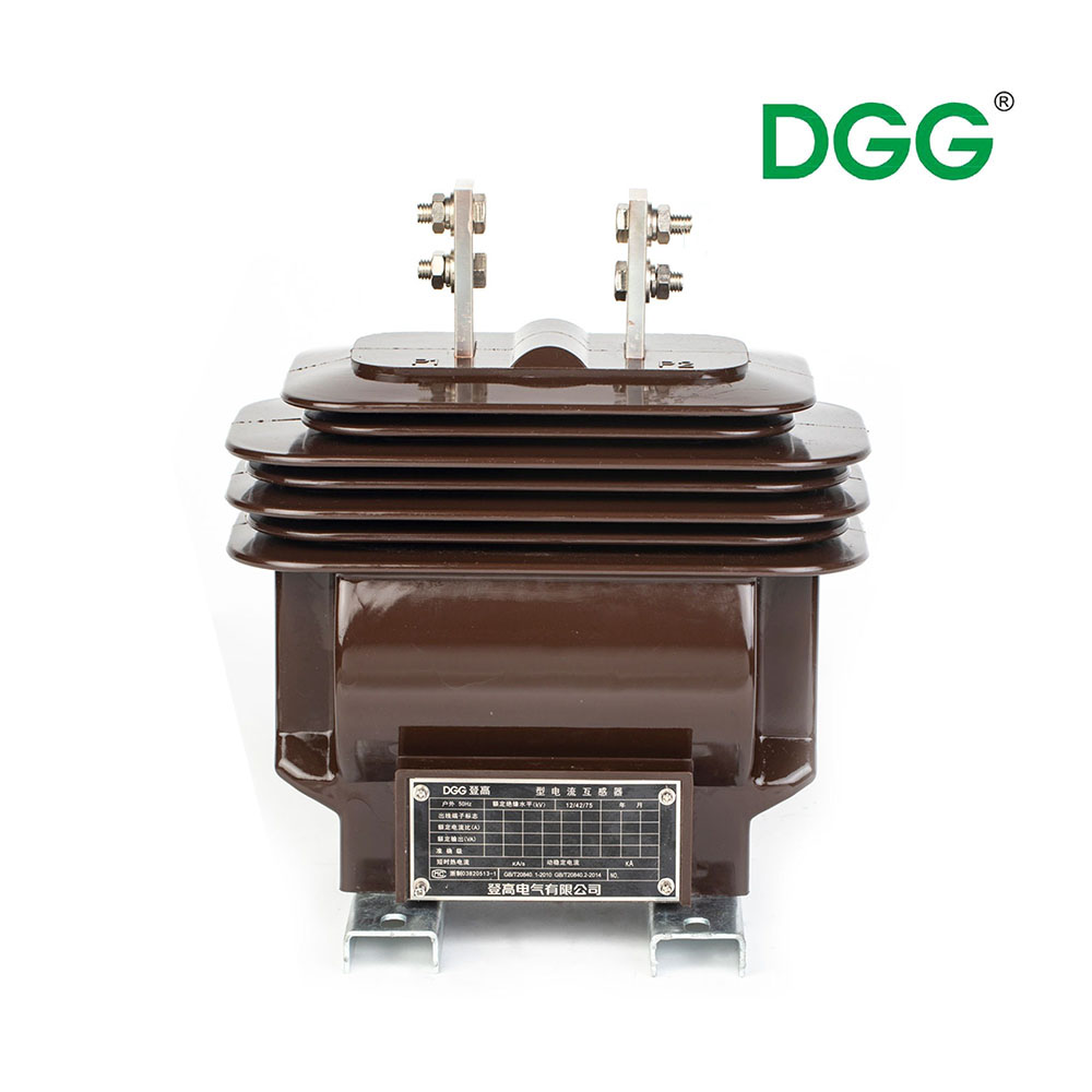
Engineers deploy various protection schemes across a power network. Each scheme demands distinct behavioral traits from the measuring devices. Understanding these differences ensures reliable relay operation.
Through-Fault Monitoring: Systems must handle faults occurring outside their immediate protection zone. We call these through-faults. The device must accurately report the high current without triggering a false trip. Stability during these external events prevents unnecessary power interruptions. The core must resist saturation long enough for downstream breakers to isolate the external issue.
Differential Protection Systems: Differential schemes monitor current entering and leaving a specific zone. They demand absolute identical response characteristics between multiple units. Any slight difference in core saturation or phase angle creates an artificial imbalance. The relay misinterprets this imbalance as an internal fault. This error triggers nuisance tripping during external faults. You must specify highly matched units for this application.
Zero-Sequence / Earth Fault Protection: Phase-to-earth faults often produce very low leakage currents initially. Core balance units detect these minute imbalances across all three phases simultaneously. The core design must capture extremely small magnetic fluxes accurately. High sensitivity remains the primary requirement here. It allows early detection of insulation breakdowns before they escalate into major short circuits.
Decision Criteria: You must align the relay manufacturer requirements closely with the unit specification. Digital relays require different burdens compared to electromechanical variants. You need to match the specified protection class precisely. Failure to align these parameters compromises the entire protection scheme.
Evaluating performance requires a deep understanding of standard technical metrics. You cannot rely on physical dimensions alone. The magnetic characteristics dictate the operational reliability.
You must differentiate between metering class and protection class devices. Metering variants provide extreme accuracy at normal operating loads. However, they intentionally saturate early during a fault. This early saturation protects the sensitive measurement instruments connected to them. Protection variants operate differently. A protection class unit, such as 5P20, must maintain its accuracy during severe overcurrents. It guarantees a maximum composite error of 5% even when the current reaches 20 times the nominal rating.
Comparison: Metering vs. Protection Class | ||
Characteristic | Metering Class (e.g., 0.2s) | Protection Class (e.g., 5P20) |
|---|---|---|
Primary Application | Revenue billing, load monitoring | Relay tripping, fault isolation |
Accuracy at Nominal Load | Extremely high (0.2% error) | Moderate (1% to 3% error) |
Saturation Behavior | Saturates quickly during faults | Resists saturation during massive surges |
Core Material Focus | High permeability at low flux | High saturation flux density |
The Accuracy Limit Factor (ALF) indicates how much fault current the unit can handle. It represents the multiple of rated current the device scales before exceeding its allowed error limit. Verifying the ALF ensures the unit matches the expected fault levels of your specific grid location. Calculating the actual connected burden remains vital to maintaining this ALF. If the connected burden exceeds the rated burden, the true ALF drops significantly.
Follow this procedure to verify burden and ALF alignment:
Determine the internal input impedance of the connected protection relay.
Measure the total resistance of the secondary copper wires running between the unit and the relay.
Add the resistance of any intermediate terminal blocks or test switches.
Calculate the total actual burden in Volt-Amperes (VA).
Compare this actual burden against the nameplate rated burden of the unit. Ensure it remains lower to preserve the specified ALF.
The Knee-Point Voltage (Vk) serves as the ultimate determinant of performance for strict differential schemes. It defines the exact point where the core begins to saturate heavily. Specifically, it marks the voltage where a 10% increase in secondary voltage requires a 50% increase in exciting current. A high knee-point voltage proves the device can drive massive fault currents through the secondary wires without collapsing.
Transient dimensioning addresses the most demanding fault conditions. Fault currents rarely present as perfect, symmetrical sine waves initially. They contain a decaying DC offset. This DC component rapidly pushes the magnetic core toward saturation. Standard calculations often ignore this factor. You must account for the transient phase. Special transient protection classes handle this DC offset effectively. They ensure the relay operates correctly during the most chaotic first milliseconds of a fault.
Standard catalog units perform well in newly designed, highly controlled switchgear environments. However, real-world infrastructure often presents unique physical and electrical challenges. In many scenarios, specifying a custom current transformer becomes necessary to guarantee system integrity.
Legacy retrofits represent a major engineering challenge. Older switchgear panels feature strict dimensional constraints. The busbar spacing might be irregular. The available window size might not accommodate standard cast-resin models. You cannot physically alter the primary copper busbars easily. Bespoke designs solve this problem. Engineers customize the internal core shape and the external casting to fit perfectly into the existing legacy infrastructure.
Non-standard burdens also demand customized solutions. Many facilities upgrade to modern digital relays while retaining legacy electromechanical infrastructure. Digital relays present a much lower input impedance than older mechanical relays. This mismatch alters the entire performance dynamic of the secondary circuit. You must design units featuring specific secondary windings to match these mixed-technology environments perfectly.
Harsh environments destroy standard electrical components prematurely. Facilities located in high-vibration zones, tropical climates, or extreme-temperature industrial plants require specialized construction. You can specify custom epoxy resin potting to prevent moisture ingress. Enhanced insulation materials prevent internal tracking and premature failure. Specialized secondary terminal configurations ensure secure connections despite constant mechanical vibration.
Vendor Selection Criteria for Custom Units | ||
Evaluation Metric | Engineering Requirement | Practical Impact |
|---|---|---|
Routine Testing | In-house primary injection and excitation curve plotting. | Guarantees the bespoke design meets the required knee-point voltage. |
Standards Compliance | Strict adherence to IEC 61869-2 or IEEE C57.13. | Ensures regulatory approval and reliable protection class certification. |
Lead Time Transparency | Clear manufacturing schedules for specialized cast-resin curing. | Prevents critical delays during planned plant shutdown windows. |
Installing these devices requires strict adherence to safety and operational protocols. Mismanagement of the secondary circuit introduces severe physical hazards and compromises network reliability.
The open secondary hazard represents the most dangerous scenario in power engineering. You must never leave a secondary circuit open while the primary conductor carries load. Under normal operation, the secondary current creates a demagnetizing flux. This balances the primary magnetic flux. Opening the circuit removes this balancing effect. The primary current immediately becomes purely magnetizing current. The core flux spikes instantaneously. This rapid change induces lethally high voltages across the open secondary terminals. It destroys the internal insulation. It sparks explosive fires. Most importantly, it poses a fatal shock hazard to any nearby personnel.
Burden mismatch represents a quieter but equally destructive risk. Engineers sometimes over-specify the length of connected cables. They might select an incorrect wire gauge. Alternatively, they might misunderstand the input impedance of the relay. Both errors increase the total secondary burden. If this total burden exceeds the nameplate rating, the core saturates prematurely during a fault. The breaker fails to trip. The protective system essentially becomes useless.
Thorough testing and commissioning remain non-negotiable. You cannot assume a unit functions correctly straight out of the box. Technicians must perform primary injection testing to verify the entire loop. They must plot the magnetizing curve to confirm the actual knee-point voltage matches the factory test report. Polarity checks ensure the directional relays operate correctly. Completing these steps prior to energization guarantees the system will perform flawlessly during an actual fault.
A protection relay is only as reliable as the data it receives. During the crucial milliseconds of a power fault, the relay depends entirely on accurate proportional scaling. If the core saturates or the secondary circuit falters, the most advanced microprocessor relay becomes completely blind. Understanding accuracy limits, transient responses, and burden matching dictates the success of your entire safety infrastructure.
We encourage you to audit your existing protection schemes thoroughly. Calculate your exact cable burdens. Verify your actual Accuracy Limit Factor requirements. Consult closely with a specialized engineering team before finalizing any retrofit or new build specifications. Addressing these technical parameters proactively prevents catastrophic failures.
Submit your single-line diagrams or specific relay requirements to our engineering experts. We provide comprehensive technical consultations. Request a detailed quote on standard models or specialized bespoke units designed precisely for your complex network environment.
A: Metering CTs deliver extreme accuracy at normal loads but intentionally saturate early during a fault. This protects delicate measuring instruments from high currents. Protective CTs are engineered to avoid saturation during massive fault surges. They maintain proportional accuracy during overcurrents to ensure protection relays receive correct data and trip the breaker.
A: A DC offset rapidly pushes the magnetic core toward early saturation. This transient phase distorts the secondary waveform. Standard units often fail here. Specialized protective variants, particularly Class PX or TP, use specific gap designs or oversized cores to handle this transient phase without blinding the relay.
A: Rarely. Differential protection demands highly matched units to monitor current entering and leaving a zone. Any slight mismatch in knee-point voltage or excitation characteristics creates artificial imbalances, causing nuisance tripping. You generally require custom or highly calibrated sets to guarantee absolute stability during external through-faults.
A: Opening the secondary circuit under load causes the core magnetic flux to spike uncontrollably. This induces lethally high voltages on the secondary terminals. It quickly destroys the internal winding insulation, sparks electrical fires, and presents a severe, fatal shock hazard to any operating personnel nearby.


